Cheap Yellow Display and Home Assistant
Chris Cowley
- 9 minutes read - 1823 wordsAs I have mentioned previously I have been been gradually Home Assistant-ifying my home. Of course, part of that means having a some control panels around. I have tried an old tablet, but was not really happy with the results. At some point I leaned about the so-called “Cheap Yellow Display” (CYD). This is a small TFT display bolted directly to an ESP32 microcontroller.
There are a few things that make this interesting:
- ESPHome support: This means it is very easy to integrate into Home Assistant.
- LVLGL support: This is a powerful graphics library that allows for complex user interfaces.
- Cheap: You can get one for about 10-15 euros.
I ordered one from AliExpress without really knowing much about it and decided I would just roll with any problems that came up. As is often the case with AliExpress, the first problem was identifying exactly what arrived. I ordered a “Freenove Bitcoin Miner NMMiner NerdMinder … something something CYD ESP32 Something”. What I got was a small yellow PCB with a ILI9341 TN TFT display on one side, and an ESP32 on the other with a bunch of other stuff:
- A microSD card slot
- A battery connector
- A couple of buttons
- A few headers for GPIO access
After some searching I found out that this was indeed a CYD board, specifically this one. So now I had it, I need to figure out what to use it for to start with. Anything for my office has a much standard of Wife Acceptance Factor, so I decided to start with a control panel for my office temperature. This is already controlled using Home Assistant using a few things:
- Target temperature is variable based on presence and time of day/week
- Current temperature is from a Dallas temperature sensor (DS18B20) that sits on my desk - still in a breadboard naturally.
Info
The code for all this is pretty long and spread over a few files, so I will not show it all here. All my ESPHome code for this is available on Github if you want to see the details. Instead I will just highlight the main points as we go along. Also, I certainly will not claim this is an ideal example of how to organise a large ESPHome project! I am still learning myself.
Display and Touchscreen
Naturally, this was the first thing I did. ESPHome has built-in support, so I just created a new device in ESPHome and started from there. I then flashed the basics to the board over USB (you need Chrome for that, and the CH340 drivers installed on Windows). Once that is done, you can do everything over WiFi.
First up was getting the display working:
light:
  - platform: monochromatic
    output: backlight_pwm
    name: Display Backlight
    id: backlight
    restore_mode: ALWAYS_ON

output:
  - platform: ledc
    pin: GPIO21
    id: backlight_pwm

spi:
  - id: spi_tft
    clk_pin: GPIO14
    mosi_pin: GPIO13
    miso_pin: GPIO12

display:
  - platform: ili9xxx
    model: ili9341
    id: my_display
    spi_id: spi_tft
    cs_pin: GPIO15
    dc_pin: GPIO2
    dimensions:
      height: 320
      width: 240
    transform:
      swap_xy: True
      mirror_x: True
      mirror_y: True
    #rotation: 270
    invert_colors: false
    show_test_card: False
    color_palette: 8BIT
    color_order: RGB
    auto_clear_enabled: False
There is quite a bit going on there, as driving a display from ESPHome us pretty complex. There are a couple of key points:
- The display runs over SPI
- You also need to configure the backlight, which has variable brightness using PWM
- If you look on Github, you wil also find the touchscreen is mixed here. For now, I am keeping that separate for clarity.
How did I put all that together? Well I actually started by trying to “vibe-code” it, but that turned out to be less than ideal. It did however show me what I needed to look for in the ESPHome documentation:
- SPI
- ILI9341 display supper
- That I needed to control the backlight
With all that, I spent an evening reading the docs and some trial and error to get something that worked.
Once that was working, I moved onto the touchscreen which, like the display, runs over SPI:
spi:

  - id: spi_touch
    clk_pin: GPIO25
    mosi_pin: GPIO32
    miso_pin: GPIO39

touchscreen:
  - platform: xpt2046
    id: touch
    spi_id: spi_touch
    cs_pin: GPIO33
    transform:
      swap_xy: False
      mirror_x: True
      mirror_y: False
    calibration:
      x_max: 3718
      x_min: 187
      y_max: 3799
      y_min: 272
Most of that should be familiar after doing the display and the information all came from the ESPHome docs. The bit that, if I’m honest, is a mystery to me is where I got platform: xpt2046 from. I think that may have been successfully guessed by ChatGPT as I cannot find any reference to is in either the Freenove documentation or on the board itself. Still, it works!
Setting the transform parameters took a bit of trial and error. I basically started with everything at false and tweaked until it worked in portrait mode with the USB port on the bottom as that seems a logical way to mount it on the wall.
Setting the calibration parameters is a little more hit-or-miss, but the process is at least well-documented.`
Info
Across both the display and the touchscreen, you should completely ignore the pin numbers here. It seems to me there is no agreed convention for which GPIO pins are used for what on these CYD boards, so you just have to check the silk screen on your own board and go from there.
Now we have a working display and touchscreen, which is really the heart of the CYD board. I suppose the next step is to do something useful with it.
Reading the temperature
As the board I ended up with has a couple of GPIO pins broken out, I decided to add a second DS18B20 to the CYD board so it could read the temperature itself and get it off my desk. the silk screen tells me that GPIO23 is available on one header, and a second header breaks out 3.3V and GND, which is what I need to wire up the sensor. The board also came with some breakout wires with JST 1.24 -> Dupont connectors which worked really well for testing. Once I got it working I snipped of the dupont connectors and soldered the wires directly to the legs of the Dallas sensor - more on that later.
Adding the sensor to ESPHome was very easy:
one_wire:
  - platform: gpio
    pin: GPIO23 # Pin connected to the DS18B20 data line

sensor:
  - platform: dallas_temp
    id: panel01_temperature
    name: "Temperature"
    update_interval: 60s
    filters:
      - offset: -1.2 # Correct because it is inside a case
    on_value:
      then:
        - lvgl.label.update:
            id: ui_temp_label
            text: !lambda |-
              char buf[16];
              snprintf(buf, sizeof(buf), "%.1f°C", id(panel01_temperature).state);
              return std::string(buf);
WHAT! Really easy? Admittedly there is some faffing around with the on_value in order to update a label field in LVGL, so that is what we will look at next. This creates a sensor with the ID panel01_temperature that reads from the Dallas sensor on GPIO23 every 60 seconds. I have also added an offset filter of -1.2 degrees to calibrate it as it is inside a case. The value of that sensor is then used to update an label with the ID ui_temp_label in LVGL.
What this shows us is how the logic between our sensors and the UI will work. Our UI will have some placeholders (in this case a label), which will be updated from the various sensors. So far all we have is a sensor that reads from a local DS1820), but these could also be entities within Home Assistant.
Connecting to Home Assistant
The temperature in my office is already variable based on presence and time of day/week, so I need to get that target temperature from Home Assistant. ESPHome makes this really easy using the homeassistant sensor platform:
sensor:
  - platform: homeassistant
    id: office_target_temp
    entity_id: input_number.office_target_temperature
    on_value:
      - lvgl.spinbox.update:
          id: office_temp_spinbox
          value: !lambda return x;
This creates a sensor with the ID office_target_temp that reads from the Home Assistant entity input_number.office_target_temperature. Whenever that value changes, it updates an LVGL spinbox widget with the ID office_temp_spinbox. This spinbox will allow us to change the target temperature from the CYD display. We will cover that spinbox in the next section.
## Building the UI with LVGL

The next step is to build something that I can interact with on the screen. We will start by simply displaying the temperature:

```yaml
lvgl:
...
  pages:
    - id: office_page
      name: "Office"
      widgets:
        - obj:
            layout:
              type: "grid"
            ...
            widgets:
              - label:
                  id: ui_temp_label
                  text: "Loading..."
                ...
You will have to check Github for the full code as it is quite long and there is a lot of styling/boilerplate (styling especially you should ask someone else, I am not a reference). As I said above, here we create an LVGL label widget, this is kept up to date by temperature sensor.
Now, let’s add the spinbox that will allow us to change the target temperature in Home Assistant:
lvgl:
...
  pages:
    - id: office_page
      name: "Office"
      widgets:
        - obj:
            layout:
              type: "grid"
            ...
            widgets:
              - spinbox:
                  id: office_temp_spinbox
                  align: center
                  text_align: center
                  text_font: big_font
                  range_from: 14
                  range_to: 20
                  #step: 1
                  rollover: false
                  digits: 2
                  decimal_places: 0
                  grid_cell_column_pos: 1
                  grid_cell_row_pos: 1
                  grid_cell_x_align: stretch
                  grid_cell_y_align: STRETCH
                  on_value:
                    then:
                      - homeassistant.action:
                          action: input_number.set_value
                          data:
                            value: !lambda return x;
                            entity_id: input_number.office_target_temperature
              - button:
                  id: office_temp_down
                  widgets:
                    - label:
                        text: "\U000F0045" # mdi:arrow-down
                        text_font: big_font
                  grid_cell_column_pos: 0
                  grid_cell_row_pos: 1
                  grid_cell_x_align: STRETCH
                  grid_cell_y_align: STRETCH
                  on_click:
                    - lvgl.spinbox.decrement: office_temp_spinbox
              - button:
                  id: office_temp_up
                  widgets:
                    - label:
                        text: "\U000F005D" # mdi:arrow-up
                        text_font: big_font
                  grid_cell_column_pos: 2
                  grid_cell_row_pos: 1
                  grid_cell_x_align: STRETCH
                  grid_cell_y_align: STRETCH
                  on_click:
                    - lvgl.spinbox.increment: office_temp_spinbox
Here we have created a spinbox widget and 2 buttons for incrementing and decrementing the value. The on_value action of the spinbox is used to update the Home Assistant entity input_number.office_target_temperature whenever the value changes. The buttons are set up to increment and decrement the spinbox value when clicked.
I use a grid layout to arrange everything nicely.
There is a huge amount of detail here, especially around styling and layout, that I have glossed over. You can see the full code on Github if you want to see how it all fits together (and what else I have done).
The majority of the work was done by reading the ESPHome LVGL documentation, especially the cookbook which is awesome.
Casing it all up
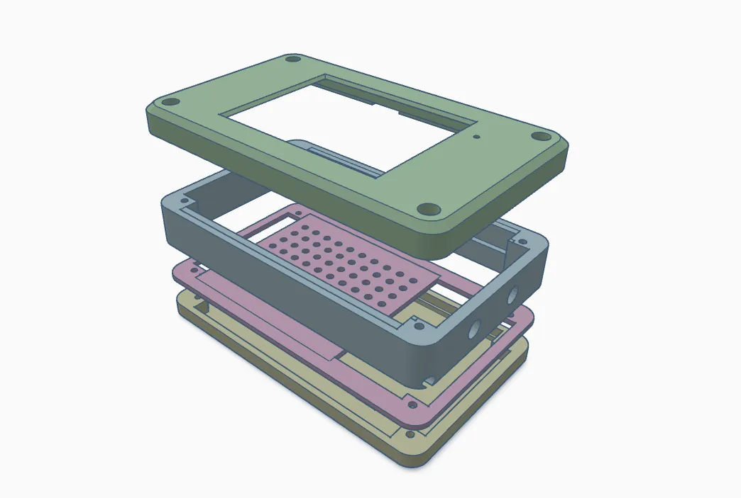
The final step was to case the whole thing up. I went with one I found on Printables called the CYD (Cheap Yellow Display) Modular Case. It is a nice design that allows the addition of a few layers for batteries, sensors, etc. I printed the front, back “Proto” layer. That way I was able to use the proto layer hold the Dallas temperature sensor.
Overall, I am pretty happy with how it turned out. The CYD board works well enough, the display displays stuff well enough and the touchscreen responds to touches. Is is a premium experience? No, but it is also dirt cheap, basically disposable and I enjoyed myself.